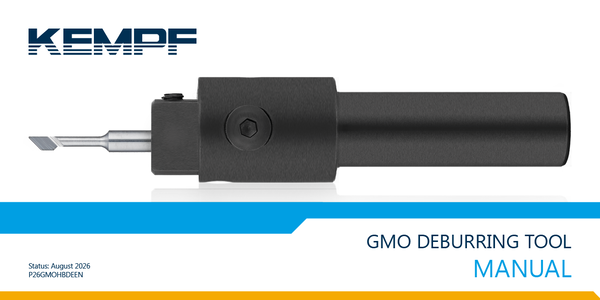
GMO Deburring Tool:
For Hard-to-Reach Bores
Precise deburring of flat and curved bore edges in hard-to-access areas and chamfering of front and back sides of holes
Your Benefits
Deburring process completed in seconds
Deburring of smallest bores from Ø 0.8 mm
Rotating tool with carbide cutting edge
Clean and process-reliable deburring
Easy handling, no special requirements necessary
Usable on any machine, ideal for CNC machines
Deburring thickness adjustable via set screws or 4 different spring strengths
Patented tooling system
Recommended for robotic applications

Video 1: Operation of the GMO deburring tool
The GMO deburring tool is designed for bore holes starting at a diameter of 0.8 mm. For different workpiece diameters, individual components can be quickly and easily changed. With four different types of compression springs (light, medium, strong, and very strong), it is also possible to adjust the tool’s contact pressure to the workpiece. The cutting circle diameter of the tool can be precisely set to the diameter to be deburred via an adjustment screw. Blades are available in various designs for the tool. This allows deburring not only of internal edges but also external edges and highly curved workpiece surfaces.
Our GMO deburring tool simulation and programming aid

|
Deburring holes with curved bore edges |
|

|
Deburring holes with flat bore edges |
|

|
Deburring bores in hard-to-reach areas |
|
|
The GMO deburring tool allows holes to be deburred using two machining methods. In most cases, working with the spring force of the installed compression spring is sufficient. Additionally, the compression spring can be replaced by an M3 screw, enabling defined chamfers to be created or larger burrs to be removed in a rigid setting. This is particularly useful for threaded bores. Regardless of the chosen machining method, the tool must be assembled and adjusted according to the hole diameter to be deburred so that the center of the front cutting edge aligns with the bore edge. |
||
|
1. DEBURRING WITH SPRING FORCE Various compression springs with different force levels are available. The spring is selected depending on the burr size or workpiece material properties. For example, a weak spring for aluminum, a strong compression spring for stainless steel. Additionally, the spring force can be adjusted via the set screw. The spring force largely determines the burr size. |
||

|

|

|
|
DRIVE IN Position the deburrer’s center axis on the bore center. Adjust the cutting circle diameter so that the center of the cutting edge aligns with the hole edge. The tool is pressed against the axis against the spring force. |
PASS THROUGH BORE
With the tool rotating and a high feed rate (approx. F=500), plunge into the bore. The front tool edge is rounded to allow easy entry and prevent damage to the outer chamfer. |
DEBURRING BORE EXIT Only drive in until the tool swings outward and the offset tool neck rests against the bore. Then retract from the bore with a low feed rate, depending on the desired deburring intensity (approx. F=100). |
|
2. DEBURRING WITH RIGID SETTING The spring is removed and replaced by the included M3 screw. The cutting circle diameter is now precisely adjusted and fixed with two screws. Optimal machine programming is possible using the tool simulation and the free programming aid. |
||

|

|

|
|
ADJUST CUTTING EDGE Position the deburrer’s center axis on the bore center. Adjust the cutting circle diameter so that the center of the cutting edge aligns with the bore edge. The spindle or workpiece must be adjusted in the Z direction so the cutting edge can pass through the bore without contact. |
PASS THROUGH BORE After adjusting the cutting edge, move through the bore at rapid traverse without rotation. |
ADJUST CUTTING EDGE
Then move the spindle or workpiece back by the adjustment value. Now start the rotation and slowly feed upward until the desired chamfer is achieved. |
|
Deburring both sides of a pipe section with the GMO deburring tool
using the standard method (with spring) |
Deburring both sides of a pipe section
with the GMO deburring tool
without spring – with rigid setting |
Video 2: Inside and outside deburring of a bore